2 Bit Parallel Adder Circuit Diagram
Adder bit parallel circuit ripple Bit adder implementation logic adders numbers circuit two bits schematic carry ripple add electronics build implement together adding stack 5-bit parallel adder ~ creative engineering projects
Binary Adder and Parallel Adder - Electrical Engineering Stack Exchange
Parallel adder Adder binary parallel bit logic diagram circuit electronics between Full adder circuit diagram
Cd4008 4-bit full adder ic pinout, working, example and datasheet
Adder serial flip flop circuit parallel binary bit logic flipflop use clock carry numbers sum two construct add electronics hasAdder circuit diagram schematic bit works figure Adder parallel schematic adders advantagesBoolean algebra.
16 bit full adder digital circuit simulation using logisim softwareAdder carry ripple subtractor overflow verilog binary redstone tutorials boolean computers begingroup Adder parallel binary serial bits gif stack first resultsAdder logic half implementation.

My technical articles: necessity of hardware description language
Adder combinational truth logic circuitverse addersAdder parallel bit diagram Adder subtractor add sub bit binary logic using subtraction combinational adders circuits tutorial electronicsBinary adder and parallel adder.
Digital logicAdder parallel bit inputs 2-bit adder implementationParallel adder bit diagram technical articles block.

Unit -2 :combinational building blocks – b.c.a study
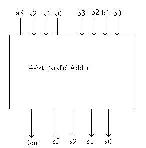
Binary arithmetic circuitsAdder logisim 😊 four bit parallel adder. 4 bit binary adder circuit / block diagramWhat is parallel binary adder?.
Adder bit four diagram parallel block ripple carry circuit binaryAdder bit gates nand implementation diagram only add Design of parallel adderAdder subtractor arithmetic binary circuits complement electronics.

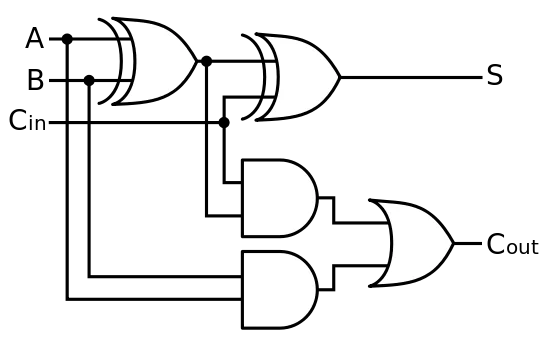
Adder circuit binary logic output xor boolean electronics diagrams derived
Binary adder/subtractorAdder parallel subtractor logic digital geeksforgeeks N-bit parallel adders (4-bit binary adder and subtractor)Adder parallel circuitverse.
Adder parallel subtractor addersFull-adder circuit, the schematic diagram and how it works – deeptronic 5-bit parallel adder ~ creative engineering projectsAdder datasheet.

5-bit parallel adder ~ creative engineering projects
Binary adder and parallel adderAdder bit parallel circuit diagram .
.

CD4008 4-Bit Full ADDER IC pinout, working, example and datasheet

boolean algebra - 2 bit adder implementation - Mathematics Stack Exchange
My Technical Articles: Necessity of Hardware Description Language

Binary Adder and Parallel Adder - Electrical Engineering Stack Exchange

5-BIT PARALLEL ADDER ~ Creative Engineering Projects

boolean - How to determine an Overflow in a 4 bit ripple-carry adder

Binary Adder and Parallel Adder - Electrical Engineering Stack Exchange