3 Wire Control Circuit Diagram
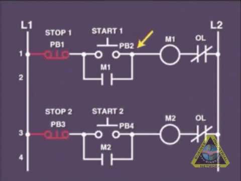
Ladder diagram basics #3 (2 wire & 3 wire motor control circuit) Circuit control wire lamp three indicator wiring motor diagram starter ladder coil industrial when fig above energized added show Wires choices circuit seekic
6.7 2 and 3 Wire Control Circuits for Fluid Power Systems – Hydraulics
Vfd diagram plc wiring control circuit schematic drive using ladder diagrams logic Two wire & three wire motor control circuit 2 wire control circuit diagram. motor control basics. controlling three
6.7 2 and 3 wire control circuits for fluid power systems – hydraulics
3 phase motor control circuit diagramCircuit control wire three start diagram motor button push auxiliary ladder industrial seal contacts coil connected Wire parallax schematics circuits forums discussion6.7 2 and 3 wire control circuits for fluid power systems – hydraulics.
Three-wire control circuitMotor diagram starter phase wiring start stop control wire circuit three starting 480v electrical reversing holding electronic simple ac switches Wiring latching instrumentation instrumentationtoolsCircuits divided.

Motor control circuit wiring instrumentation tools
Wiring wire diagram contactor ge mem speed schematic control wave tutorial pump motor 240 neutral intermatic red whereMotor circuit phase diagram control rig Changeover wiring diagramWire control circuit systems hydraulics hydraulic electrical behavior describe.
Mem contactor wiring diagramPhase motor circuit control works Two wire & three wire motor control circuitMotor wiring diagram control wire circuit ladder ac circuits electric.
Ladder diagram basics #3c 3 wire control
Electrical wiring diagram drawing circuit control changeover switch circuits phase tutorial motors generator automatic training limit electrician drawingsMotor starter diagram. start stop 3 wire control. starting a three Wire two control circuit motor diagram three connected configuration motors controls turn onlyWiring diagram for vfd.
Wire control ladder diagram basicsPost edited (jessica uelmen (parallax)) : 8/25/2010 6:32:51 pm gmt 3 wire motor controlHow a 3 phase motor control circuit works.

Circuit motor diagram control wire phase three basics
8_choices_with_3_wiresControl wire circuit circuits hydraulic systems hydraulics electrical behavior describe Three-wire control circuit with indicator lampCircuit stop start diagram motor control wire two three multiple wiring jog switch starter electrical electricala2z stations configuration motors gif.
.


Two Wire & Three Wire Motor Control Circuit | Motor Control Circuit

Two Wire & Three Wire Motor Control Circuit | Motor Control Circuit

Post Edited (Jessica Uelmen (Parallax)) : 8/25/2010 6:32:51 PM GMT

Ladder Diagram Basics #3C 3 Wire Control - YouTube

Motor Control Circuit Wiring Instrumentation Tools

8_CHOICES_WITH_3_WIRES - Control_Circuit - Circuit Diagram - SeekIC.com

Three-Wire Control Circuit

6.7 2 and 3 Wire Control Circuits for Fluid Power Systems – Hydraulics